Function(PRESS DIE)
![]()
![]()
![]()
![]()
![]()
![]()
![]()
![]()
Function(PRESS DIE)
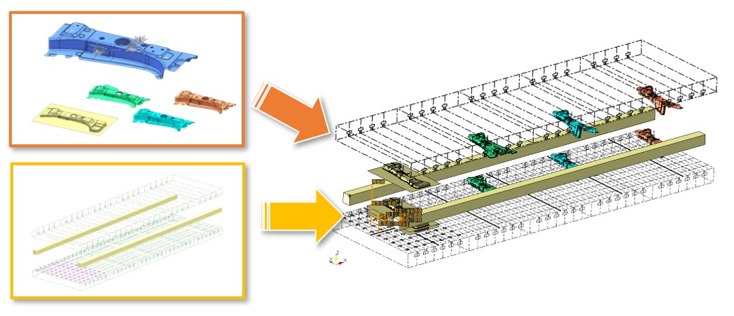
DL, a 3D supporting tool, is used for improving quality of die layout design during the design stage. The tool enables the System operators to previously check and examine 3D images and output 3D result data, before acutally pressing a metal sheet into shapes and transferring the press-formed metal sheet to a subsequent process.
This "3DDL Support" function serves the System operators to improve the operations in the subsequent processes by using the 3D result data.
The previous examinations and responses ensure a process of manufacturing without re-work.
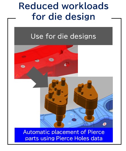
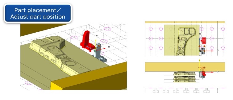
※CADmeiste2022 is strenthened by commands in the subsequent processes for automatically positioning Pierce Parts and adjusting and finalizing positions of die parts tentatively put by DL designers based upon Pierce Holes data assigned by DL designeds to each process. The Company will continuously support efficient operations through coodinations between commands of DL design and those of die design.
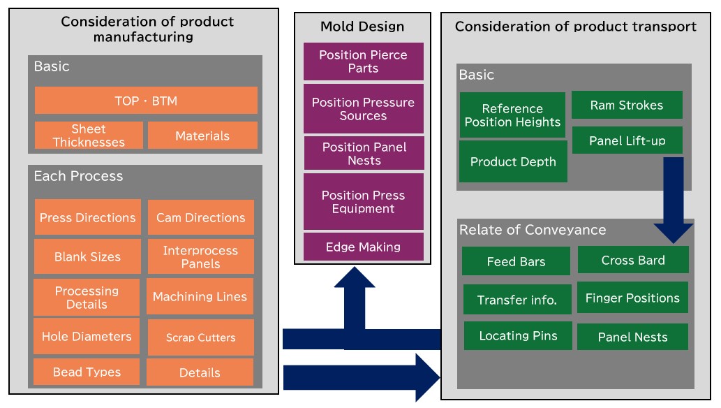
Mold design can effective use of cushion pin placement、height of standard position、Part Location Consideration for mold design and DL data with confirmed transport.
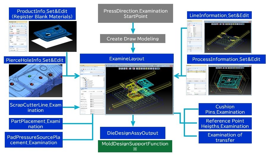
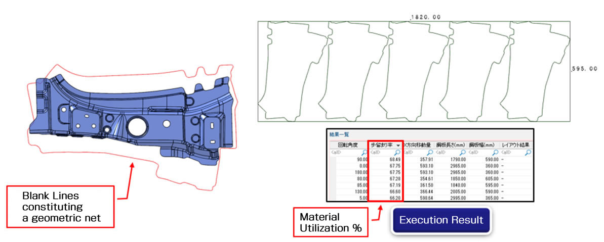
Input data of a geometric net composed of blank lines. This function uses the input data in order to compute a layout of blank-line geometric nets on a steel plate.
The function computes and indicates use efficiency (hereinafter referred to as “material utilization”) % of a steel plate.
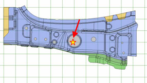
This capability enables users to calculate the center of mass based on the data of model shape, and decide the starting point.
The commands enable consideration of the press/cam directions without pending or compromising the processes of assessment.
It has the capability of suitably adjusting the unit and sequence of rotation even if a die layout designer indicates a press direction for rotation angle of a model through the use of number of decimal places.
The data can be output in XML or CSV formats.
DL has the embedded capabilities below for assessment during the phase of process design.
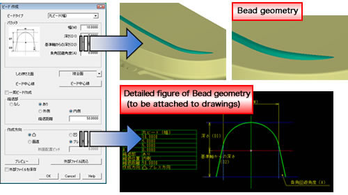
This command enables a simultaneous creation of Bead geometry and detailed figures thereof through simple operations. The detailed figures will be attached to drawings
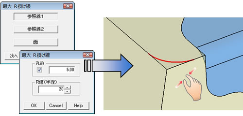
This command enables a creation of a curve that indicates a maximum of R for fillet processing. The curve can be created through intuitive operations of input.
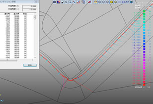
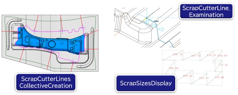
The “ScrapCutterLineExamination” command enables the System to display automatically Scrap Cutter Lines on the basis of data about Drawn Surface, Trim Lines, Blank Inflow Lines, Scrap Sizes. Furthermore, the System operators can adjust intuitively reference positions, angles, etc.
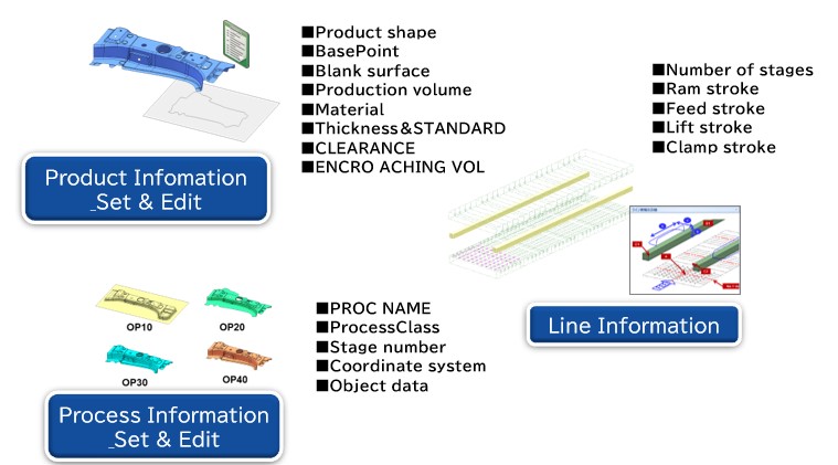
The "SetData" command can set and edit nesesary information for 3DDL.
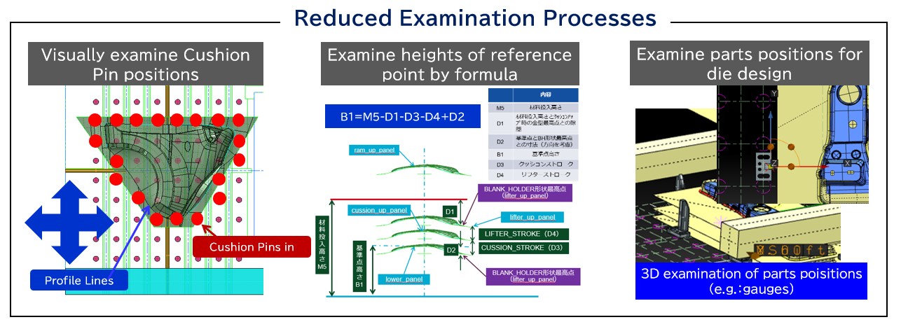
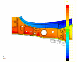
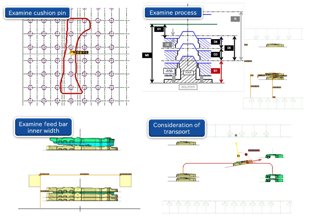
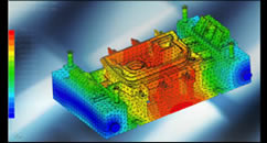
The “LayOutExamination” command enables the System operators to visually examine three-dimensionalized layout images in light of examining cushion pins, processes, feed bar inner width, transference between processes and parts positions.
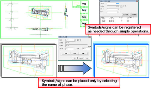
Placing symbols/signs at each drawing is bothersome.
This command enables an easy one-time placement of symbols/signs in each drawing of individual phases through simple operations. Users can register their symbols/signs that they use.
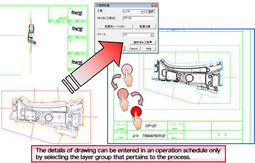
Creating operation schedules is bothersome.
This command enables an easy creation of operation schedules through intuitive operations.
If you have any inquiries about our product or would like to request a visit to your place for explanation or demonstration, please use the inquiry form.
![]() Inquiry form
Inquiry form


 Official site