Function(CAM)
![]()
![]()
![]()
![]()
![]()
![]()
![]()
![]()
Function(CAM)
3DPROFILE creates data for machining along 3D Profile Lines/Curves of a press die, machining with a trimming cutter blade, machining a relief.
3DPROFILE even creates machining paths that keep a cutter from colliding with shaped portions of a subject to be machined such as those referred to as Structures. Thus, 3DPROFILE may suffice in a site of machining.
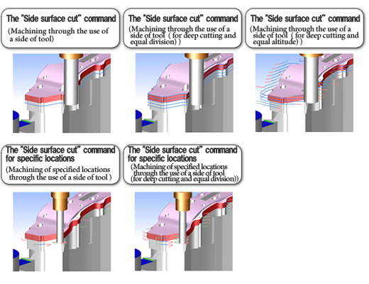
Paths for performing contour machining with a trimming blade can be created through the use of the side of tool.
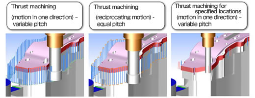
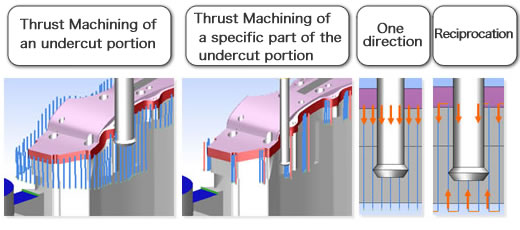
Paths to perform Thrust Machining with a trimming blade are created through the use of Vertical Tools.
A path for machining an undercut section where it is as wide as a trimming blade can be created, provided that the blade position of undercut machining tool is controlled.
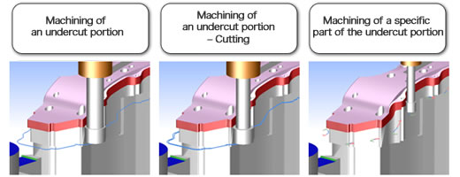
The machining methods create a path that enables the use of an undercut machining tool without causing interference against the trimming blade. The path continues to be as wide as the width of trimming blade. The path also supports re-iteration of a thrust machining of undercut portions.
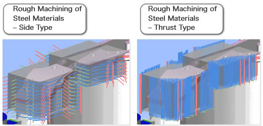
Paths for roughly machining steel materials can be created by executing the command for machining contours (the "CONTOUR" command) or the command for Thrust Machining (the "Plunge Machining" command).
Paths for performing helical machining for long holes or anomalous holes can be created in accordance with the outlines of holes.
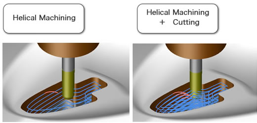
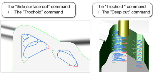
The capability of trochoid machining has been provided in order to decrease the tool load of cutting corners.
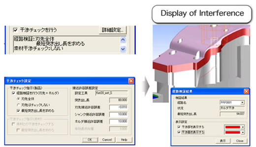
Check functions have been provided in order to prevent machining troubles such as tool breakage.
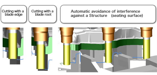
Interference Check
Interference can checked between a tool (blade edge or tool holder) and a model surface or a seat surface when paths are created. The System enables an unmanned machining based upon creating safe paths that keep cutters from collision (interference).
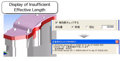
Check of Tool Effective Length
A tool breakage can be prevented by comparing the effective cutting length of a blade against the width of cut. A shorter effective length than the width of cut will cause a tool breakage. In this case, the necessary effective length (safe effective length) is calculated.
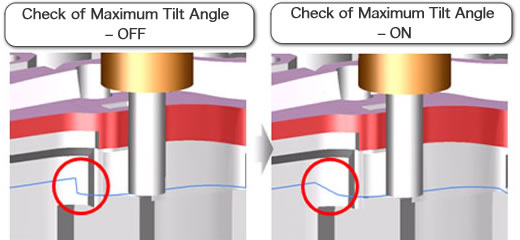
Check of Maximum Tilt Angle
This function prevents a machining tool from suffering a surge of stress due to a rapid change in angle of the titling areas where it is operated.
This automatically avoids interference between a product and a tool.
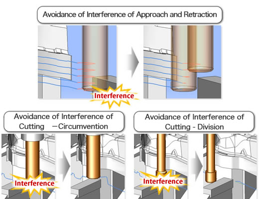
The System uses specific cutters suitable for machining-subject areas in light of inclingation angles of Profile Lines and a cutter width.
It machines a flat part through the use of a short blade portion close to a cutter hilt (referred to as 'Neck Root Cutting'). The System moves a long blade cutter along contours in order to machine slanted parts. (Slopes mean a heavy duty for cutters. ) Thus, the System enables machining paths that match machining subject shapes.
This function automatically creates constituents for a part subject to machining, based upon Profile Line colors and types, belt surface colors and machining features. Thus, the function automatically creates paths from rough machining to finishing machining.
Reference Solids
The System automatically creates 3D Profile Lines/Curves (profile lines/curves and range demarcation lines/curves based upon 2D Profile Lines /Curves that it understands by viewing a solid shape in a design phase.
Thus, the System does away with preparations partly through creating profile lines/curves and range demarcation lines/curves based upon 2D Profile Lines/Curves projected on product surfaces.
Standard Procedures Automatic Decision
This function automatically assigns a standard procedure composed of machining processes to automatcially specified constitutents of machining-subject part.
This command automatically identifies a presence or absence of interference around a cutting tool at the top of a machining proess tree and a presence or absence of islands that require separate machining paths in closed part constituents. Thus, it automatically decides an optimum standard procedure.
If you have any inquiries about our product or would like to request a visit to your place for explanation or demonstration, please use the inquiry form.
![]() Inquiry form
Inquiry form


 Official site